Reverse engineer an NZXT Keyboard
Comprendre et réimplémenter un protocole RGB propriétaire
Introduction
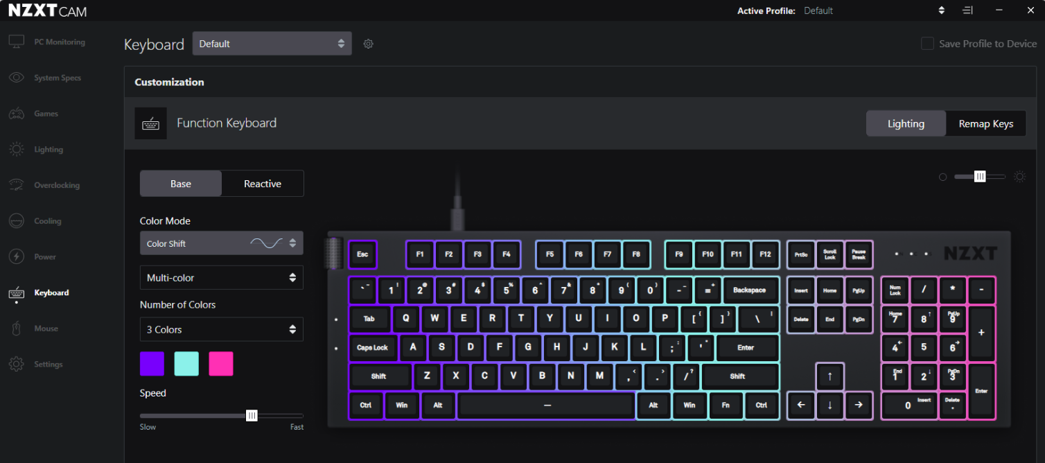
This project stems from the “simple” desire to play with ambilight or other advanced effects on my NZXT Function keyboard.
Unfortunately, as always, the protocol is proprietary, and the keyboard can only be controlled through the manufacturer’s app (NZXT Cam). Even more regrettably, no one in the community has yet reverse-engineered this well-known keyboard or any other NZXT RGB keyboard.
Fortunately, with Wireshark, the proprietary tool, a bit of AI, and some packet replay capability, we have more than enough to understand the protocol.
Proprietary Tool and Capturing an RGB Control Frame
The proprietary functions are quite limited.
To capture the RGB exchange, we need to:
- Change the driver to use a classic USB driver (winUSB in my case)
- Wireshark with libusb installed (requires a restart…)
The driver replacement is easily done with Zadig.
Warning: After changing the driver, it may be difficult to reinstall the proprietary driver (usually, uninstall the device via Windows and possibly reinstall NZXT Cam).
To identify the keyboard in Wireshark, we must find the right interface to capture; my only solution is to listen on all interfaces and see which one responds only to a key press on the keyboard or a color change, which is quite fast.
Now, when changing the color of a single key in Cam, we see these packets:
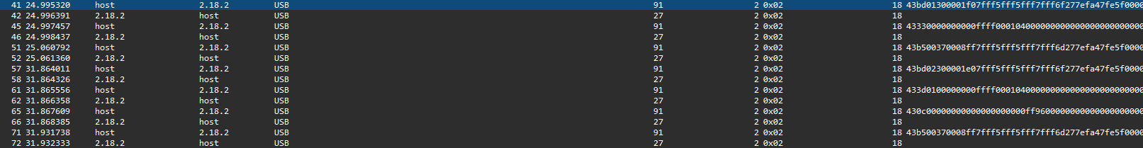
We observe that:
- The RGB packets are URB_INTERRUPT
- The exchange format is request / acknowledgment
- A repetitive sequence is noticed with what seems to be commands (3b etc.)
Extraction of Basic Information
To replay the packets later, we first need:
- The vendor ID
- The product ID
- The interface for the RGB
- The endpoint for the RGB
- The input endpoint for the RGB (used for acknowledgments in our case)
The vendor ID and product ID can be found in the GET DESCRIPTOR Response DEVICE packet sent when the keyboard is plugged in.
The interface and endpoint can be found in the GET DESCRIPTOR Response CONFIGURATION packet, but there are several:
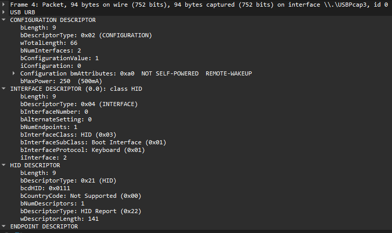
The interface/endpoint function is as follows:
| Info | Value |
|---|---|
| Vendor ID | 0x1e71(NZXT) |
| Product ID | 0x2106 |
| Interface ID | 0x01 |
| Endpoint ID OUT | 0x02 |
| Endpoint ID IN | 0x82 |
Replay and Modification of Packets
Using the previous basic information, let’s write an initial connection script using libusb:
#include "libusb.h"
#define NZXT_FUNCTION_KEYBOARD_RGB_SEND_ENDPOINT     2
#define NZXT_FUNCTION_KEYBOARD_RGB_RECV_ENDPOINT 0x82
#define NZXT_FUNCTION_KEYBOARD_DATA_SIZE 64
#define NZXT_FUNCTION_KEYBOARD_RGB_INTERFACE_ID 1

int main() {
    libusb_context* ctx = nullptr;
    libusb_device_handle*     handle = nullptr;

    libusb_init(&ctx);

    handle = libusb_open_device_with_vid_pid(ctx, 0x1e71, 0x2106);
    if (!handle) {
        libusb_exit(ctx);
        return;
    }

    // Auto-détache kernel driver
    libusb_set_auto_detach_kernel_driver(handle, 1);

    // Claim cette interface
    if (libusb_claim_interface(handle, NZXT_FUNCTION_KEYBOARD_RGB_INTERFACE_ID) < 0) {
        return;
    }

    // CODE

    libusb_release_interface(handle, NZXT_FUNCTION_KEYBOARD_RGB_INTERFACE_ID);
    libusb_close(handle);
    libusb_exit(ctx);
}
With following send / receive functions:
void send(libusb_device_handle* handle, unsigned char* rgb_data) {
    int transferred = 0;
    int res = libusb_interrupt_transfer(
        handle,
        NZXT_FUNCTION_KEYBOARD_RGB_SEND_ENDPOINT,
        rgb_data,
        NZXT_FUNCTION_KEYBOARD_DATA_SIZE,
        &transferred,
        1000
        );
    if(res != 0) {
        LOG_ERROR("libusb_interrupt_transfer error: %s", libusb_error_name(res));
    }
}

void receive(libusb_device_handle* handle) {
    int transferred = 0;
    for (int i = 0; i < 1; i++) {
        unsigned char data_in[64] = {0};
        libusb_interrupt_transfer(
            handle,
            NZXT_FUNCTION_KEYBOARD_RGB_RECV_ENDPOINT,
            data_in,
            NZXT_FUNCTION_KEYBOARD_DATA_SIZE,
            &transferred,
            100
            );
    }
}
Next code will be replacing the placeholder //code
To “play” with the data:
unsigned char test_data[64] = {
    0x43, 0xb5, 0x00, 0x37, 0x00, 0x08, 0xff, 0x7f,
    0xff, 0x5f, 0xff, 0x5f, 0xff, 0x7f, 0xff, 0x6d,
    0x27, 0x7e, 0xfa, 0x47, 0xfe, 0x5f, 0x00, 0x00,
    0x3d, 0x00, 0x02, 0xff, 0xff, 0xff, 0x07, 0x00,
    0x00, 0x00, 0x00, 0x00, 0x00, 0x00, 0x00, 0x00,
    0x02, 0x00, 0x00, 0x00, 0x00, 0x00, 0x00, 0x00,
    0x00, 0x46, 0x00, 0x03, 0x02, 0xff, 0xff, 0xff,
    0x00, 0x00, 0x00, 0x00, 0x00, 0x00, 0x00, 0x00
};
send(test_data)
receive()
The receive operation must be placed after each request (otherwise, the keyboard won’t accept anything).
Seeing the keyboard react means that the sending is correct.
Protocol Analysis
Through replay, monitoring, and analyzing the actual behavior, we can deduce certain commands:
- 43,b5,00,37: Allows reusing NZXT Cam after a write (probably needed for a proper write)
- 43,bd,00,30: Color of the first packet
- 43,1d: Continuity color
- 43,3d: Continuity color (with 3 colors)
With the following format:

(packet 1 at the top, packet 2 at the bottom)
- Each payload is 64 bytes.
- The color settings are actually a single repeated sequence throughout the packets, always in the same format:
- mode: The mode of the entire key set
- keys: Bitmap representing each key
- color: Basic RGB
By experimenting with the modes, we deduce the following: - 0x01: Static - 0x02: Off / Unknown - 0x03: Rainbow - 0x04: Breathing
For the keys bitmap, each byte represents 5 keys; to turn on key 1, we set: 0b00000001, to turn on keys 1 and 2, we set the second bit, etc. (using a binary OR).
Chaining the Packets
To define multiple colors and achieve true per-key settings, we need to send multiple packets (the first packet defines 2 colors, the second defines 3 colors, etc.). Sending a first packet 0x43,0xbd followed by 0x43,0x3d seems functional up to the fourth packet (i.e., 9 colors). The solution seems to involve listening for the code for each packet (bd, 3d, 0c, etc.) up to the 23rd (each key with a different color).
My problem is that currently, with all my tests, I can’t reconnect the keyboard to Cam (even with the functional driver); it seems the driver is very sensitive to what the keyboard responds…
For now, let’s start by implementing a basic OpenRGB plugin.
Implementation in OpenRGB
The implementation of RGB controllers is not very well documented (the main documentation is here).
However, the code is quite readable on its own, so let’s continue with libusb; my tests with hidapi, recommended by OpenRGB, haven’t been successful.
QtCreator imports the project well, and once the Visual Studio C++ SDK is installed, the project is immediately recognized with the correct build profile.
Let’s start by creating the base of the controller:
- Simply copy another controller, for my part the Clevo Keyboard.
- Remove all its “useful” code.
- Replace the names, identifiers, etc.
This results in the following file structure in my case:
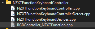
Then, begin implementing the detector.
Create the detector
The whole plugin is imported through this function:
REGISTER_HID_DETECTOR_IPU("NZXT Function Keyboard", DetectNZXTFunctionKeyboardControllers, 0x1e71, 0x2106, 0, 0x001, 0x006);
It will append a callback function called when the vendor ID, the product ID are correct.
Callback constructor:
void DetectNZXTFunctionKeyboardControllers(hid_device_info* info, const std::string& name)
The callback:
NZXTFunctionKeyboardController*     controller     = new NZXTFunctionKeyboardController(*info);
RGBController_NZXTFunctionKeyboard* rgb_controller = new RGBController_NZXTFunctionKeyboard(controller);
rgb_controller->name                         = name;

ResourceManager::get()->RegisterRGBController(rgb_controller);
Two distinct elements are defined: - The controller: the backend of the protocol. - The Device: inherited from RGBController, it maps the OpenRGB functions and required properties to our device.
The RegisterRGBController function adds the controller to the OpenRGB interface.
Implementing the Device
The device itself is not very interesting; it mainly consists of adapted generic code. Only the DeviceUpdateLEDs method is noteworthy.
The DeviceUpdateLEDs() function:
std::map<std::tuple<int, int, int>, std::vector<unsigned int>> leds_states_by_color; // {(R,G,B): [indexes]}

for(int i = 0; i < NZXT_FUNCTION_KEYBOARD_NUM_LEDS; i++)
{
    auto rgb_tuple = std::tuple<int,int,int>(RGBGetRValue(colors[i]), RGBGetGValue(colors[i]),RGBGetBValue(colors[i]));
    if(rgb_tuple == std::tuple<int,int,int>(0, 0, 0)) {
        continue;
    }
    if(leds_states_by_color.find(rgb_tuple) == leds_states_by_color.end()) {
        // Append the color to the list
        leds_states_by_color[rgb_tuple] = std::vector<unsigned int>({leds[i].value});
    } else {
        // Append the led to this color
        leds_states_by_color[rgb_tuple].push_back(leds[i].value);
    }
}

controller->SendColors(leds_states_by_color, modes[active_mode].brightness);
To obtain the color of the LEDs, we need to use RGBGet<R/G/B>Value, and we store the three in a tuple. Then we gather the LEDs by color. Note that I do not use <i> the index of the LED but leds[i].value, which corresponds to the layout.
Implementing the Protocol
The best part, which ultimately just reuses the code I already have, with the following modifications:
- Open the device in the constructor.
- Close the device in the destructor.
The send and receive functions remain exactly the same, now implemented as methods of the controller.
We also need to add functions to obtain SerialString, Firmware version, etc. (mine are approximate).
Then there’s the function SendColors(std::map<std::tuple<int, int, int>, std::vector<unsigned int>> leds_states_by_color, unsigned char brightness):
First, we prepare the payloads for the packets, which looks like this:

By simply adding the data for each color.
std::deque<unsigned char> leds_bytes;
for(auto e : leds_states_by_color) {
    auto color = e.first;
    auto leds = e.second;
    std::vector<unsigned char> bitmap(16, 0); // Keys *16
    //unsigned char bitmap[16] = {0};
    for(auto led_id : leds) {
        int byte_index = led_id / 8;
        int bit_index = led_id % 8;
        bitmap[byte_index] |= (1 << bit_index);
    }

    leds_bytes.push_back(0x01); // Mode
    leds_bytes.insert(leds_bytes.end(), bitmap.begin(), bitmap.end()); // Key * 16
    leds_bytes.push_back(0x00); // Padding
    leds_bytes.push_back(0x00); // Padding
    leds_bytes.push_back(std::get<0>(color)); // Color
    leds_bytes.push_back(std::get<1>(color)); // Color
    leds_bytes.push_back(std::get<2>(color)); // Color
}
Then create the whole packets:
std::deque<std::vector<unsigned char>> packets;
bool begin = true;
while(leds_bytes.size()) {
    std::vector<unsigned char> packet(64, 0);
    size_t payload_offset = 5; // Different for the first packet

    if(begin) { // First packet is different
        begin = false;
        packet[0] = 0x43;
        packet[1] = 0xbd;
        packet[2] = 0x00; // Other packets to send count
        packet[3] = 0x30; // Padding
        packet[4] = 0x00; // Padding
    } else {
        packet[0] = 0x43;
        packet[1] = 0x3d;
        packet[2] = 0x00; // Other packets to send count
        payload_offset = 3;
    }
    size_t bytes_to_move = (std::min)(leds_bytes.size(), size_t(64-payload_offset));
    std::copy(leds_bytes.begin(), leds_bytes.begin() + bytes_to_move, packet.data() + payload_offset);
    leds_bytes.erase(leds_bytes.begin(), leds_bytes.begin() + bytes_to_move);

    packets.push_back(std::move(packet));
}

for(int i = 0; i < packets.size(); i++) { // Define packet counts
    packets[i][2] = packets.size() - (i+1);
}
The second loop defines, for each packet, the number of packets that follow.
Now, we just need to handle the sending:
for(auto packet : packets) {
    send(packet.data());
    receive();
}
receive();
unsigned char final[64] = {
    0x43, 0xb5, 0x00, 0x37, 0x00, 0x08, 0xff, 0x7f, 0xff, 0x5f, 0xff, 0x5f, 0xff, 0x7f, 0xff, 0x6d, 0x27, 0x7e, 0xfa, 0x47, 0xfe, 0x5f, 0x00, 0x00, 0x3d, 0x00, 0x02, 0xff, 0xff, 0xff, 0x07, 0x00, 0x00, 0x00, 0x00, 0x00, 0x00, 0x00, 0x00, 0x00, 0x02, 0x00, 0x00, 0x00, 0x00, 0x00, 0x00, 0x00, 0x00, 0x46, 0x00, 0x03, 0x02, 0xff, 0xff, 0xff, 0x00, 0x00, 0x00, 0x00, 0x00, 0x00, 0x00, 0x00
};
send(final);
receive();
receive();
The last raw packet corresponds to the packet I use to ensure that Cam recognizes the keyboard again after a custom set (it validates the registration or similar).
Defining the OpenRGB Key Mapping / Bitmap ID
Simple but tedious, I had to find out which hardware ID corresponded to each OpenRGB key:
For this, I simply reused my initial script, making this loop into useful code:
while (true) {
    int wanted_key;
    std::cin >> wanted_key;
    std::cout << "Turning on key " << wanted_key << std::endl;
    memset(leds_bytes, 0, NZXT_FUNCTION_KEYBOARD_NUM_LEDS*3);
    leds_bytes[wanted_key*3] = 255;
    send_keys(handle, leds_bytes, 100);
}
By simply using 1, 2, 3, etc., each key lights up in red, and then I can directly map the following array:
layout_values nzxt_function_keyboard_offset_values =
{
    {
        /* ESC          F1    F2    F3    F4    F5    F6    F7    F8    F9   F10   F11   F12   PRSC  SCLK  PSBK                         */
        0,         1,   2,   3,   4,   5,   6,   7,   8,   9,   10,   11,   12,   13,  14,  115,
        /* BKTK    1     2     3     4     5     6     7     8     9     0     -     =   BSPC  INS   HOME  PGUP  NLCK   NP/   NP*  NP-  */
        16,   17,   18,   19,   20,   21,   22,   23,   24,   25,   26,   27,   28,   30,   46,   126,   99,    100,   101,   102,  103,
        /* TAB     Q     W     E     R     T     Y     U     I     O     P     [     ]     \   DEL   END   PGDN   NP7   NP8   NP9   NP+ */
        32,   33,   34,   35,   36,   37,   38,   39,   40,   42,   42,   43,   44,   62,   62,   104,   105,    106,   97,   113,  114,
        /* CPLK    A     S     D     F     G     H     J     K     L     ;     "     #   ENTR                     NP4   NP5   NP6       */
        48,   49,   50,   51,   52,   53,   54,   55,   56,   57,   58,   59,    60,   61,                      116,   117,   118,
        /* LSFT    \     Z     X     C     V     B     N     M     ,     .     /   RSFT             ARWU          NP1   NP2   NP3  NPEN */
        64,    65,   66,   67,    68,    69,   70,    71,    72,   73,   74,   75,   77,               78,          119,   120,   121,  123,
        /* LCTL  LWIN  LALT               SPC              RALT  RFNC  RMNU  RCTL              ARWL ARWD   ARWR   NP0         NP.       */
        80,    81,    82,                85,                89,    90,   91,    92,               93,   94,   110,    124,         122
    },
    {
        /* Add more regional layout fixes here */
    }
};
Now OpenRGB can control each key individually (up to 9 different colors as mentioned earlier).
Importing into Artemis
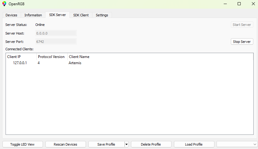
Artemis simply handles the “artistic” control of the keyboard. To use it, you just need to install it and the OpenRGB plugin. In OpenRGB, start the API server:
Again, the OpenRGB / Artemis mapping is not correct, so I need to create one based on an existing configuration.
This time it’s simpler because the ID is not hardware but logical. Indeed, instead of being mapped to the key Artemis …_ESCAPE, the escape key corresponds to CustomKey1, and this pattern holds for the entire keyboard.
I simply reused an existing full-size keyboard mapping for key positions and renamed it in the XML file:
<?xml version="1.0" encoding="utf-8"?>
<Device xmlns:xsi="http://www.w3.org/2001/XMLSchema-instance" xmlns:xsd="http://www.w3.org/2001/XMLSchema">
<Name>NZXT Function TEST</Name>
<Description />
<Author>Patch</Author>
<Type>Keyboard</Type>
<Vendor>NZXT</Vendor>
<Model>Function</Model>
<Width>437</Width>
<Height>156</Height>
<Leds>
  <Led Id="Keyboard_Custom1">
    <X>4</X>
    <Y>33</Y>
    <CustomData xsi:type="LayoutCustomLedData">
      <LogicalLayouts>
        <LogicalLayout Name="NA" />
      </LogicalLayouts>
    </CustomData>
  </Led>
  <Led Id="Keyboard_Custom2">
    <X>+19</X>
    <CustomData xsi:type="LayoutCustomLedData">
      <LogicalLayouts>
        <LogicalLayout Name="NA" />
      </LogicalLayouts>
    </CustomData>
  </Led>
  ...
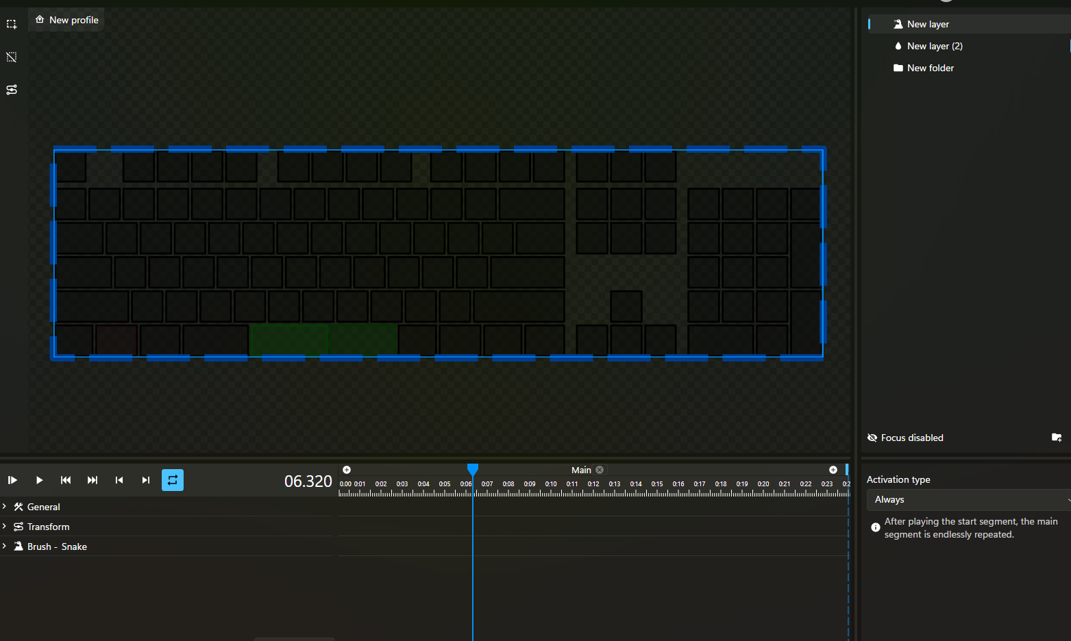
Here is the result with a snake effect:
Conclusion
I am somewhat satisfied; I would have liked to achieve true ambilight, for example, but the maximum of 9 colors limits me. There is probably a solution, at least by reusing the manufacturer’s packets, but I no longer have access to them.
Overall, I am glad to have been able to understand a USB protocol from scratch; I have to be content with that :)
Appendix & Sources
- OpenRGB: https://gitlab.com/CalcProgrammer1/OpenRGB
- My fork: https://gitlab.com/P-atch/OpenRGB